Three Farmhouses: A Study in Passive Solar Design
By Karl North
Interest in passive solar design, once limited to a few engineers and tinkerers, expanded in the live-lightly-on-the-land movement of the 1970s and even spawned a literature on the subject. Since then, interest has waned to the point where most activity is not getting the public visibility that it deserves.
This trend is unfortunate because as the energy descent from the oil era deepens, the conventional sources of heat in residences will become too expensive. The greater part of residential energy use, at least in cool climates, is for heating for various uses — space heat, hot water, cooking and drying, and cold season growing. Heat from the sun supplemented with wood heat can fulfill all these functions. To do so, housing will need passive solar initial design or makeovers.
The need for these changes is not yet well understood. Human consumption of planetary resources is now coming up against hard physical resource limits, with the following implications for home heating:
All fossil fuels will gradually become too scarce to be affordable for heating[1]
As human society returns to reliance on biomass energy for many purposes, wood and other forms of biomass will become scarcer as well
Unlike direct heat from the sun or biomass burning, other sources including “alternatives” like wind or solar electric heating require technologies that are expensive and energy conversions that waste energy, which makes them too costly for most people
As fossil energy becomes more scarce, economies that currently can produce resource-intensive alternatives will no longer have the industrial capacity to provide these technologies at the necessary scale. The only answer is to use lower cost technologies.
The heroes of the old era were builders of the technologies with the most power, regardless of how much of the earth’s finite resources they consumed. The heroes of the new era will be rebels against resource depletion, people who build and share technologies that serve basic human needs of food and shelter with the least consumption of the earth’s scarce resources.
The time is therefore right for renewed pursuit of passive solar design, a low-technology heat source for the new era. Seeking a relatively low-technology existence, in the last four decades I have constructed or rebuilt three farmhouses using passive solar designs, each adapted to different environments, available materials, and my pursuit of low-input farming. This is an attempt to share my design experiences in a way that helps people to find passive solar solutions that fit their circumstances. By covering three projects that span forty years of personal history, this saga exposes a learning process that may help the general public think about how to make their heating costs more affordable. While not intended to be a how-to manual, it hopefully will persuade non-professionals that they can work out their own energy solutions.
My account differs from many in several respects. First, it emphasizes relatively inexpensive solutions, many of which are accessible to amateur owner-builders. The first two projects were achieved with little cash outlay. They are examples of models that are increasingly valuable as the end of the era of cheap energy imposes a search for simpler solutions to such basic necessities as food and shelter. The fact that I have no training or experience as a professional builder or architect may give encouragement to others who consider this kind of building project. Second, other accounts, often written by engineers, demand extensive mathematical calculation. In the end their calculations still fail to capture the many considerations that are specific to each building project. In my experience, beyond a small number of critical dimensions and proportions that I cite in the tables and text, a good understanding of the principles of passive solar design and of the environmental conditions of the building site are sufficient to guide design within the constraints of what the owner can afford. Finally, this account reflects the potential, in a world where everything is connected, to solve problems like home energy use by designing elements to serve multiple functions as part of an integrated whole. Thus the total effect of the essential elements of passive solar design listed below will be limited by its weakest one. For example, extra investment in high quality windows is justified only if all other elements are built to the same standard.
A Review of Design Essentials
Here is a reminder of the main elements of effective passive solar design to help the reader evaluate the relative success of each of the construction projects to be described. A glossary at the end of this account provides brief definitions of words underlined in the text but does assume that the reader has an introductory knowledge of the concepts of passive solar design. I will cover details of the principles involved as they apply differently to each house. The essentials are:
A landscape that shelters the house from prevailing winds.
A compact house plan whose south side is roughly twice the area of the east or west sides.
A high percentage of south-facing glass that combines insulating value (R value) with high solar heat gain (e.g., double-paned uncoated thermopane).
Heavy insulation everywhere that heat could escape to the outdoors.
Movable insulation on windows to limit heat escape in sunless times.
Sufficient thermal mass to allow capture and storage of excess heat for use in sunless hours.
Overhangs to shade windows from the summer sun.
Air-tightness and related controls of ventilation.
A means of heat redistribution throughout the living space.
The most efficient and sustainable source of supplemental heat possible (usually local firewood).
Project 1: Canaveilles, Pyrénées Orientales, France

Figure 1. The Village of Canaveilles
In the attempt to flee responsibilities of citizenship in a country that had used weapons of mass destruction to commit genocide and horrific environmental damage in poor, Third World countries of Southeast Asia, in 1973 I left an academic career path and moved with my wife and children to begin an agrarian life in a small village in the mountains of French Catalonia. The houses of the region, with their thick stone and clay walls and heavy slate roofs, are a testament to a bygone age of heroic struggle and tenacity in an intensely sunlit but difficult terrain, using primarily the simple materials that the mountain offered in abundance. Nearly abandoned after centuries of peasant subsistence farming, the village of Canaveilles, located at an altitude of 3500 ft, offered one of these houses and a barn, all attached to other houses in the clustered style of villages of old Europe. We bought the house and barn next door and began to rebuild it as we learned to farm the narrow terraces of the steep Mediterranean mountainside.
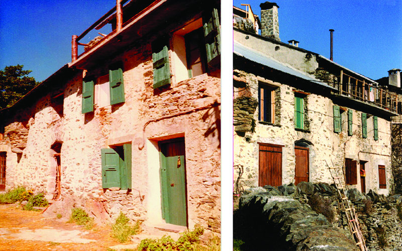
Figure 2. South face of farmhouse in Canaveilles with third storey reconstruction for passive solar heating
Insulation and Thermal Mass. The house offered some ideal requisites of passive solar design. The front wall had full southern exposure to the intense sun of the region, but being two feet thick, it kept out the both summer heat and the freezing temperatures of winter nights. The earth sheltered house has long been a favorite of energy efficient house designers. This house, in fact the whole street, was as if built to order. The north wall, chipped into the mountainside, provided the insulation equivalent of an endless earth berm. The side walls, shared with the neighbors, also supplied the high insulation values that are necessary to passive solar design. The mountainside behind the village sheltered it from the prevailing winds. All these elements in combination with the forgiving Mediterranean climate (shirtsleeve temperatures on cloudless winter days) reduced the solar heat requirement and made our first design project easier.
Compared to recommendations for thermal mass in the passive solar literature, the centuries-old, massive stone walls of this dwelling were overkill. The experience taught us that no amount of excess thermal mass hurts house performance. Our rule of thumb learned in practice has been to cover as much of the south side of a house with glass as we could afford, then build in enough heat storage to handle the solar capture capacity of the south glass area.
Solar Glazing. Traditional construction in the village had minimized window area, partly because the local subsistence farmers could not afford much glass, and partly because property was taxed according to window area. So our main task was to increase the glass area in the south face. Instead of the arduous task of tearing out thick stone walls, we chose to raise the roof (which needed replacing) on the third story garret and make that floor into our main living space, solarizing it with glass all across the front and adding a balcony.
Building the new living space was an exercise in the use of free and salvage materials, for our finances were no better than those of the remaining villagers. The river bank in the gorge below the village supplied free sand for the mortar to raise the walls. Wall stone came from ruins in the village. Rights as property owners gave us access to timber for beams and rafters in the village communal forest. Work parties of volunteers from around the region helped place the big beams, and helped with the heavy labor of removal of the old slate roof in exchange for room and board. In an abandoned commercial building in the region we found windows at salvage prices, but large enough to be used as French doors, and installed them as the south wall of the living space. I include these details because they illustrate a low-cost approach to building (and to life) that will become increasingly necessary in the post-petroleum era.
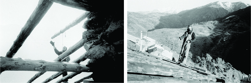
Figure 3. House reconstruction using trees from the communal forest and personal labor
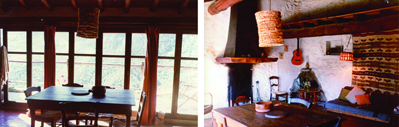
Figure 4. Finished reconstruction of third storey as main living space

Figure 5. Author on balcony enjoying February sun
Heat Distribution. We used a method that is common in passive solar design for effective heat distribution — an open, partitionless plan of the living space to serve multiple functions: cooking, dining, sitting, and a loft as a guest sleeping area. Supplementary heat came from a small wood-fired kitchen range at one end of the space and a hooded fireplace in the local Catalan style at the other. The thick stone walls kept temperatures in the lower floors warm enough in winter and cool enough in summer for sleeping and storage with no need for solar or other heating.
The weakest part of the design was the roofing, which had to be cheap asphalt tiles, as we had not the consummate skill necessary to put back the slate roof. We could not afford a plywood deck, so we used cheap planks, which were not airtight, and no insulation. In a colder climate these would have been major defects. The main problem with the new roof in the climate of southern France was lack of protection from the summer heat.
The climate in the Eastern Pyrénées is mild enough that we could forego insulating glass and movable insulation on the glass front. Instead it needed drapes and a substantial roof overhang to protect the living space from the heat of the summer sun. Despite freezing winter temperatures at night and on cloudy days, the need for supplemental heating was low enough that firewood could be sawed and split by hand. The huge thermal mass of the house was more than sufficient to maintain warmth in winter and keep the house cool in summer, but would have worked better had we been able to insulate the roof, or reinstall the slate roof on a thick bed of clay, in the tradition of the region. The experience taught us not to take lightly centuries-old construction traditions.
Having been brought up in wooden houses, we found the experience of living within the permanence, security, and quiet of massive masonry walls unforgettable. Similarly, the feeling of being almost outdoors that the wall of French doors conveyed, in combination with the balcony just outside affording a spectacular panorama of a gorge rising to often snow-capped peaks, made living in the renovated house in Canaveilles a special experience. The French doors, the balcony, earth berms, and masonry walls were design elements that we would try, with varying success, to carry on to the next passive solar farmhouse project in upstate New York.
Project 2: Freetown Corners, New York
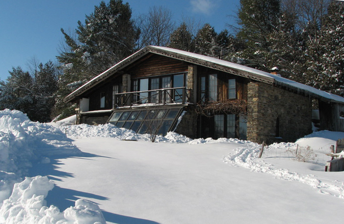
Figure 6. The farmhouse in Freetown Corners
In 1980 we moved from apprenticeship with low-input farming and building in France to commercial farming in the US. Purchase of empty, long-abandoned farmland gave us a clean slate with which to design and build. We were accustomed to the fairy-tale quality of old European villages and farms that nestled naturally into the countryside, a consequence of a long process of adaptation whereby human habitat finds its best “fit” both to the lay of the land and to the aesthetic needs of the inhabitants. The planner of a small farm has an opportunity that is unusual in our industrial age to design both an enterprise and a habitat that is satisfyingly human in scale. A farmhouse, barns, and farm-stead layout built to complement and celebrate the natural beauty of the spot rather than conquer it are a joy to live and work in, and this was our plan. We had enough capital from the sale of the house in France to cover construction of a farmhouse because we furnished most of the labor, contracted to thin state forest plantings for low-cost saw logs, collected local stone from old walls, and bought used windows, doors, and other fixtures at salvage prices.
The Landscape. The colder, almost continental climate of Central New York required the fullest implementation of passive solar design principles. A first energy efficiency design problem on our windswept hilltop land was to locate the farmhouse and buildings in a place sheltered from the prevailing winds. This we accomplished with some effort by building in the lee of a small evergreen woods a quarter of a mile back from the road and by planting a shelter belt of spruce and pine saplings in the adjoining hedgerow. Putting the center of operations out of the winter wind chill was well worth building the extra lane, for it made the house easier to heat and our winter farm work enjoyable.
Thermal Mass. Our intent was to build a mostly masonry residence, for its thermal mass and for the other qualities we had discovered in European architecture. We also incorporated the dug-in feature of the Canaveilles house, which in this site meant partially covering the back and one side wall with earth berms.
The masonry consists of an insulated stone floor on the ground level and a shell of concrete block on three sides, insulated heavily on the outside and covered with a second wall of stone where walls were not earth-sheltered. We left rafters and beams as whole logs for strength and to save sawmill costs. Another staple of European architecture that we managed to incorporate was arched openings. We built them the traditional way in the laid stone walls, and in the block walls we poured concrete into forms, using a piece of sheet metal in the bottom of the form, curved in the shape of an arch. At this point people said that the structure looked like a large bird spreading its wings either for take-off or to defend a brood.

Figure 7. Dry-laid block and bonding cement make strong walls fast
Solar Glazing. An attached solar greenhouse was a major addition to our solar building experience. It merits careful treatment here because such a structure poses unique design challenges. Our passive solar plan was to cover most of the front, south-facing wall with glass. We are convinced that an attached greenhouse is an essential of passive solar design because of its multiple functions. Built to the same design standard for insulation and double glazing, a greenhouse can capture as much heat as other south windows, without overheating the main living space. Designed with slanted glass, it provides even more heat to the interior than vertical glass because for most of the year the sun hits it more directly. The extra sunlight from slanted glass is often too much in the living space of a house, but it improves three potential functions of a greenhouse — to indirectly heat the house, to grow food and flowers, and to provide solar heated water. Finally, provision for many plants in a house freshens inside air: plants and animals have a symbiotic respirational relationship; the stale exhale of each is the fresh air to inhale of the other.
We sank our greenhouse four feet below grade to serve several purposes. It creates a shaded space along the front for plants that require more indirect light. It allows taller plants and a stepped set of growing benches that makes better use of the space and light. And, like the earth berms on other house walls, it adds the insulation value of the ambient earth temperature and reduces insulation costs for the underground parts of the walls.
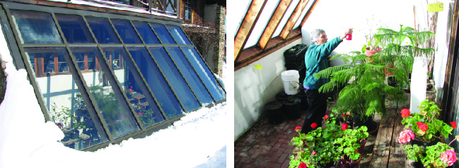
Figure 8. The professionally reglazed New York greenhouse
Although slanted glass lets in more heat than vertical glass, it has drawbacks that are an important design consideration. More exposed to the weather than vertical glass, it takes more construction skill and expense to make it weather tight. Our original construction of salvage glass on an entirely wood frame served the purpose well for 15 years. But leaks and rot in the frame took their toll, and when we could afford it, we replaced the front frame, roof, and glass with a professional job. It has lasted many years with virtually no deterioration but was much more expensive. The present version shown in the photos consists of:
High quality, relatively rot proof framing wood.
Thermopane double glazing.
Special hardware for the glass to ride on as it expands and contracts at a different rate from the frame in the typically wild swings of greenhouse temperatures.
A sheet metal external skin for further weather protection.
Movable insulation is also more of a challenge with slanted glass. Placed inside, it is harder to move and in many cases subject to soaking with window condensation. Placed outside, it needs to be weather proof and easily movable and cleanable of snow and ice. We chose not to insulate, but without it the greenhouse temperature drops to 40 °F at night and takes longer to reheat and to begin heating the house on sunny winter days. This makes the greenhouse less of a source of heat for the house than it would be with movable insulation. As nearly half the south-facing glass is in the greenhouse, we now see this as a major design flaw. There are of course technological solutions to these problems (motorized operation, specialized insulation materials and hardware), but not ones we could afford at the time.
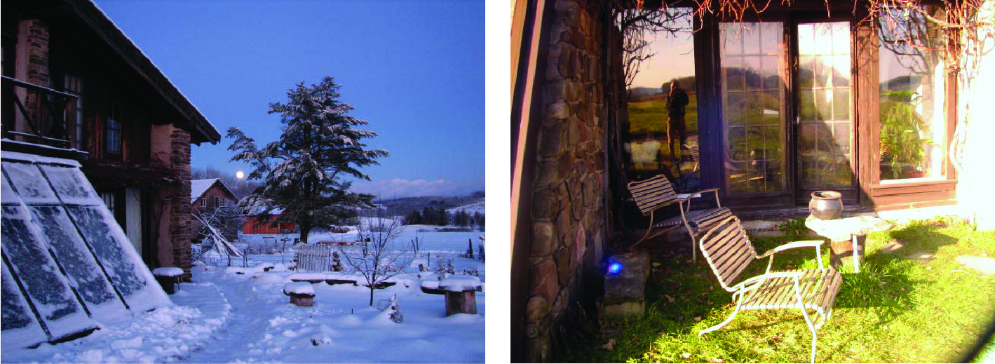
Figure 9. Sloped glass gathers snow (left); grapevine shades let light through in winter (right)
To alleviate the problem, we designed the common wall between the greenhouse and the main house to include openable windows to light the kitchen and to control transfer of heat between the two spaces. Like movable insulation, these openings must be managed almost daily but work well. Sloped glass collects snow but is easily swept with a long-handled push broom. It also needs a shade cloth cover against the summer heat.
Our building plan for the farmhouse called for 400 ft2 of glass, mostly placed on the south side. To stay within budget, we acquired used glass: standard 3’x6’ thermopanes whose seals had broken and let in dirt over years of use and several sets of used French doors obtained through a want ad. We separated the thermopanes into single panes to clean them and to have enough to single-glaze all fixed window space. To achieve the double glazing standard of passive solar design, we installed plastic sheeting on wood frames in all these windows. When later we were able to replace these windows with new thermopane, we were gratified to discover that our makeshift originals had kept heat in the house as well as the new ones.
The French doors were a different story. Although performing perfectly their romantic function, they were not built for exterior use, were single-paned, and could not seal well enough to meet the high standard of air-tightness required in energy-efficient design. Our solution to this problem was to close them permanently for the winter, apply weather stripping, and attach a permanent second pane of plexiglass on the exterior.
The house was still not designed to be sufficiently airtight, partly because we had been able to ignore the problem in the relatively mild French climate and did not take it seriously enough in cold New York. The main leaks were around the home-built main external door and in the all-important roof. Here again, there were easy solutions, but at the time they cost more than we thought we could afford. In retrospect I think building an airtight house is important enough to have warranted the extra expense.
Passive Hot Water. Next to heating the house, hot water production is often the largest residential energy consumer. A house designed to be heated by the sun supplemented by firewood can easily incorporate use of the same sources to heat water, so we designed the New York house to take full advantage of these on-site energy sources. The most effective source of winter hot water, common in many houses before the advent of cheap fossil energy, is a wood-fired kitchen range that also heats the house and cooks the food. The best of these are constructed of cast iron to retain heat and incorporate a water jacket in the firebox through which water is piped to heat it. The water jacket is connected by a convection loop to a tank placed above the stove. The fact that water rises when heated causes constant circulation of water in the loop and hot water accumulation in the tank, without an extra pump. As in conventional hot water systems, the tank delivers hot water to sinks and shower because it is part of the pressurized water system of the house.
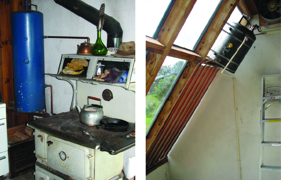
Figure 10. Winter and summer hot water systems (New York house)
The summer hot water system makes use of the slanted glass in this greenhouse and a location protected from heat loss (inside the greenhouse in this case), both of which are necessary to extract enough solar energy to sufficiently heat the water. A flat plate collector, which is an arrangement of pipes with fins to aid solar absorption, connects to a tank above it, and it uses the same convection loop principle as in the winter system to accumulate hot water in the tank. Like the winter system, it is part of the pressurized water system of the house. Most solar hot water collectors must be located outside the house to obtain the proper angle to the sun and need an insulated enclosure and special designs to prevent freezing. This system avoids those costly complications.
Supplemental Heat. Our wood-fired kitchen range built entirely of cast iron (see photo) is second only to a masonry heater in efficiency because of its long smoke path, which allows the cast iron to absorb heat and keep it in the house, then radiate it gradually. Sustainability is high because the stove doubles as a cooking fire for half the year in this climate.
Overhangs. In houses that contain so much sun-trapping glass, overhangs are essential to keep the house from overheating in the summer. The overhangs must extend far enough to shade the glass from the high summer sun, but not so much as to block the lower winter sun.
The size of the overhang depends in part on the latitude of the house location, which determines the angle of incidence of the sun. Tables of the angles of incidence at the summer and winter solstices at different latitudes should be basis for designing the amount of overhang. The other design factor is the distance of the overhang above the window, because a higher overhang will shade less. In fact, because the distance of our chalet roof above the second floor center windows varies, it failed to protect them despite a full 4 foot roof overhang, as one can see in the summer photo of the house.
Since an overhang is impractical on slanted glass, we dropped a shade cloth on the greenhouse in the summer. Above the other first floor windows, rather than a roof we built a frame and trained grape vine to cover it with leaves. The winter photo (Figure 9) shows the leafless vine letting in the sun.
Air Control and Heat Distribution. Management of air flow is important in passive solar design, both air entry into the house and its distribution throughout the rooms and through the thermal mass to store heat effectively. Two techniques that we tried did not work well for various reasons, although they are proven concepts. I will describe them briefly because they will play an important role in the third house in this saga.
Our first idea was to provide air to the house through 100 ft of underground 4 inch pipe to locations near the kitchen range and a Rumford fireplace. The long underground passage warms the air to the earth temperature of 45 °F instead of direct entry at much colder average winter air temperatures. Chimney draft from the wood fires draws in the air, helped with a fan as necessary. In a more airtight house, this technique would have worked better. In this house, the fires could more easily draw in air from poorly sealed doors instead.
The other idea was to counteract the heat stratification that can occur in buildings of more than one story, so that upper floors tend to get more heat. This is a typical design problem of passive solar construction, where open floor plans allow warm air to move around the house from its sources, the south windows and wood stoves. Using small fans in two locations, we used the hollow block walls of the New York house as channels to bring the warm air that collected at the top of the house down through the walls and under the stone floor, storing some of it in the masonry on the way. This would have worked better if the air had not lost much of its heat to the walls before it reached the bottom of the house. Two alternative solutions, a building design that controlled air movement between floors, or placement of the heated living space on a higher floor as we did in France, were not possible in New York due to site constraints.

Figure 11. Heat distribution openings between greenhouse and kitchen (New York house)
Movable Insulation. Initially we built light wood frames filled with bubble pack and covered with colored cloth, which fit tightly into the vertical windows. These worked well for years. Eventually they wore out from constant moving, and a specialist in the trade made us insulating quilts that could be let down like Venetian Blinds and clamped on all sides. Because of the irregularities of our rustic construction techniques, none of these solutions were as airtight as we would like, but then the windows themselves were not completely airtight either.
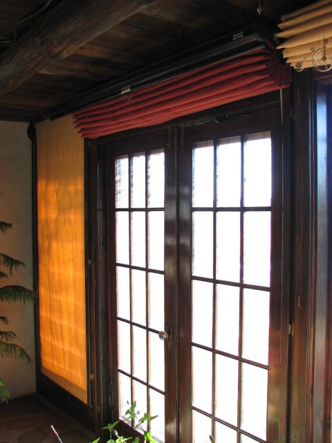
Figure 12. Movable insulation (New York house)
| Heated floor area | 1000 ft2 |
| Wall, foundation and underfloor insulation | R = 28 |
| Roof insulation | R = 35 |
| Thermal mass | Stone floor and 2500 concrete blocks in walls |
| South facing glass | 400 ft2 |
| Other glass (East window) | 10 ft2 |
Table 1. Specifics (New York House)
Despite its limitations, the house performed well enough to completely solar heat itself on sunny, frigid winter days, and used no more than two full cords of supplementary wood heat per year, mostly burned in a vintage, high quality cast iron kitchen range. We paid more attention to dimensions and proportions that are critical to passive solar design than we did in the Mediterranean climate. The table lists these for comparison with the third house that I will describe and with other designs in the literature.
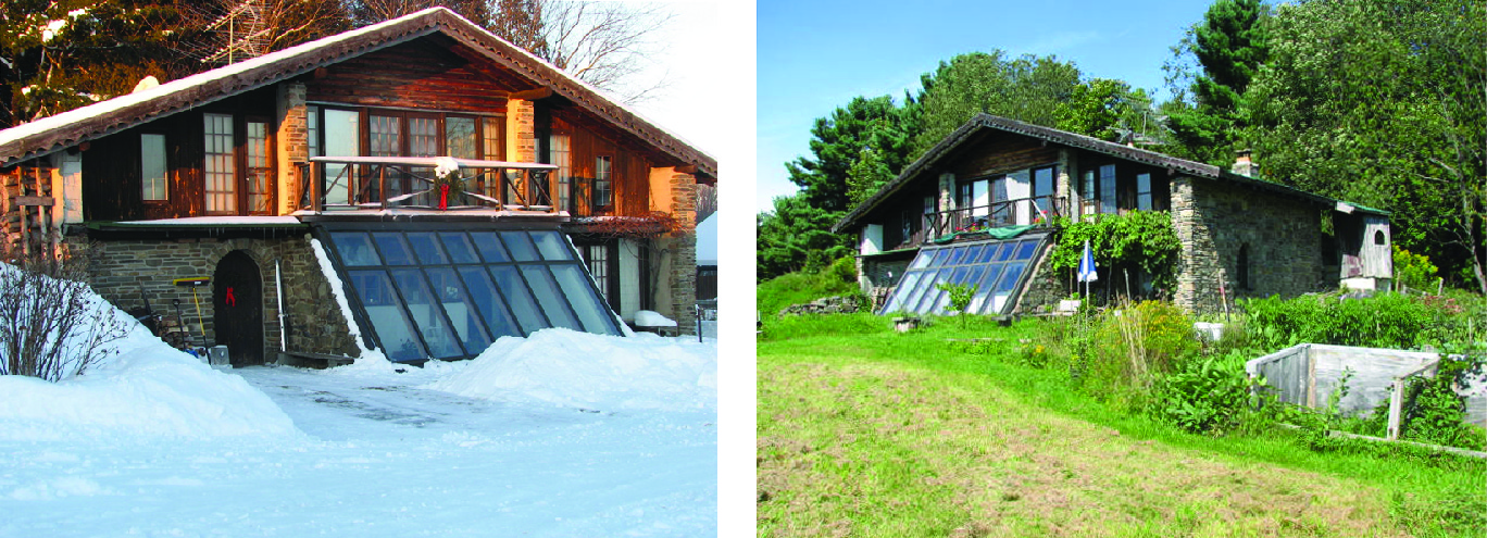
Figure 13. Seasonal views of the New York farmhouse
Most of the limitations of our passive solar plan for the New York farmhouse were deliberate choices to limit costs. In that regard, we succeeded in our goal to build without debt. The cash outlay to build the house, mostly for materials and a small amount of machine labor, was an affordable $15,000 in 1980 dollars. Today the concrete block alone would cost that much.
Project 3. A Professionally Built House in Far Downeast Maine
In 2011 we designed a house for a farmstead two miles from the sea and the Canadian border, and we acted as general contractor to oversee its construction. Although the location is farther north than the New York house, the moderating effect of the many surrounding bays and lakes makes for a similar climate. Like the New York house, its hilltop location is partly sheltered by forest from the prevailing winds.
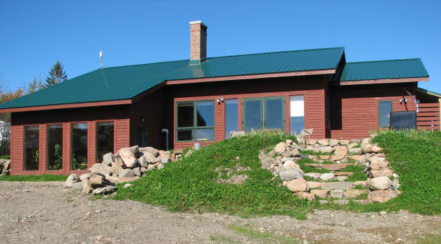
Figure 14. South face of the Maine farmhouse in mid-October
The design gains from all our previous experience and from improvements in passive solar design ideas, standards, and materials since we built in 1980. We were also able to invest in better quality and in passive solar elements of higher energy efficiency than we could in the previous houses. In particular, this farmhouse gains from the adoption of a unique way of integrating thermal mass devised by an engineer/builder, James Kachadorian. He successfully tested the design in a number of houses that he built in New England and wrote a book on the subject, which we used as a guide.[2]
The cost of this house, however, was far greater than the others in this study, because we had to pay professional builders and abide by building codes and professional standards of finished carpentry, which previously we had been able to avoid by doing our own work, using free and salvage materials and building to more rustic standards. So I do not pretend this house to be a model of inexpensive passive solar construction. Although new to passive solar design, the builders carried out our plans successfully so that the house performs as expected. I think the fact that this design uses mostly conventional materials and construction practices was critical to their success.
This house is a one-story stud frame building set on a concrete foundation. A thermal mass consisting of a concrete slab floor and subfloor concrete block area is insulated from the foundation. The frame is covered with a raised truss roof. All of these elements involve standard construction techniques but required some alterations to fit our design.
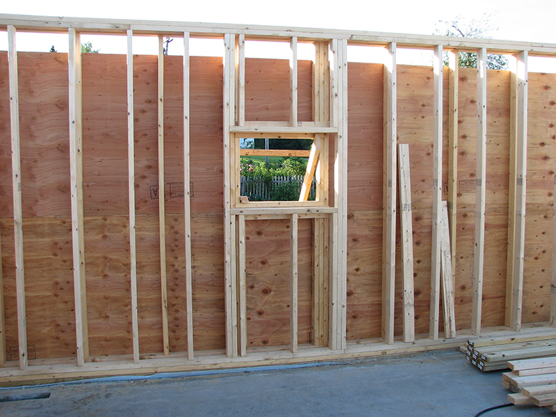
Figure 15. Double-walled frame (Maine house)

Figure 16. Raised truss design (Maine house)
Insulation. Current standards for energy efficient housing call for super-insulation. Wall insulation of R=40 and insulation of ceilings to R=80 are said to be worth the cost in energy savings. To come close to these levels with our choice of blown-in cellulose insulation, we had to build a double-walled frame 10 inches thick. The two wall frames are tied together with wide sills and top plates. We used different stud spacing for the inner and outer walls (see photo) to offset them and reduce heat loss through the studs. To provide enough space for insulation above the ceiling, we used a raised truss design that allowed for 20 inches of cellulose, especially in the critical area where the truss space narrows at the bottom of the roof where it meets the top of the wall. Dense-packed in with a blower, the cellulose flows around framing and fills all spaces. Although cellulose insulation is recycled paper goods and therefore promoted as “green,” it was not particularly cheap. As the photo shows, large quantities are needed to achieve the desired standard. However, an owner-builder could achieve a similar result by stuffing wall spaces with bags of dry leaves, quantities of which are available in town neighborhoods at no cost.
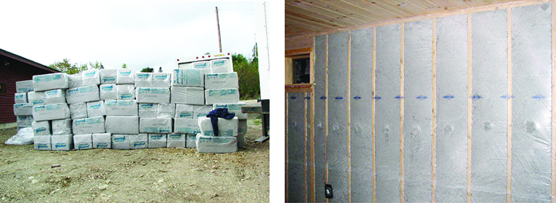
Figure 17. Cellulose insulation, as delivered (left) and packed in a wall behind a vapor barrier (right)
Thermal Mass and Heat Distribution. In its original concept, the Kachadorian design uses the convection loop created by air heated by sun coming through the bank of south windows. The heated air rises, pulling air through concrete blocks laid in channels under a poured concrete floor and storing heat from the room air in this mass of masonry. Registers along the north and south edges of the house floor allow air to enter the thermal mass at the north edge and exit below the south windows. Because air in convection loops follows the path of least resistance, we suspected that in the Kachadorian design most of the air would flow across the top of the floor to replace the rising air, following the normal path of least resistance of the convection loop in a house and rendering the block channel storage mass ineffective.
To make sure that air flows through the block channels, we altered the design as shown in the sketch. We placed a plenum across the middle of the subfloor system from east to west. This is a central duct (metal in the photo) that feeds the channels in the block. In the center of the house we built a vertical duct containing a quiet, variable speed fan that takes the warm air from the ceiling and pushes it down through the plenum, through the block, and out the registers at the edges of the floor. This design performs the double function of moving the warmest air into the thermal mass and allowing us to close registers in different rooms of the house to distribute stored heat differently to the floor in each room.
As shown in Figure 18, rigid foam completely insulates the block and poured floor from the foundation and the earth, which allows the masonry to retain heat that is absorbed from the airflow and also from the sun directly hitting the concrete floor. The floor is permanently stained a dark color to maximize absorption of the sun’s radiant heat. Over time, the transfer of heat by these two routes brings the thermal mass up to room temperature and stabilizes the house temperature by releasing heat and keeping the temperature from dropping far when there is no sun or artificial heat.
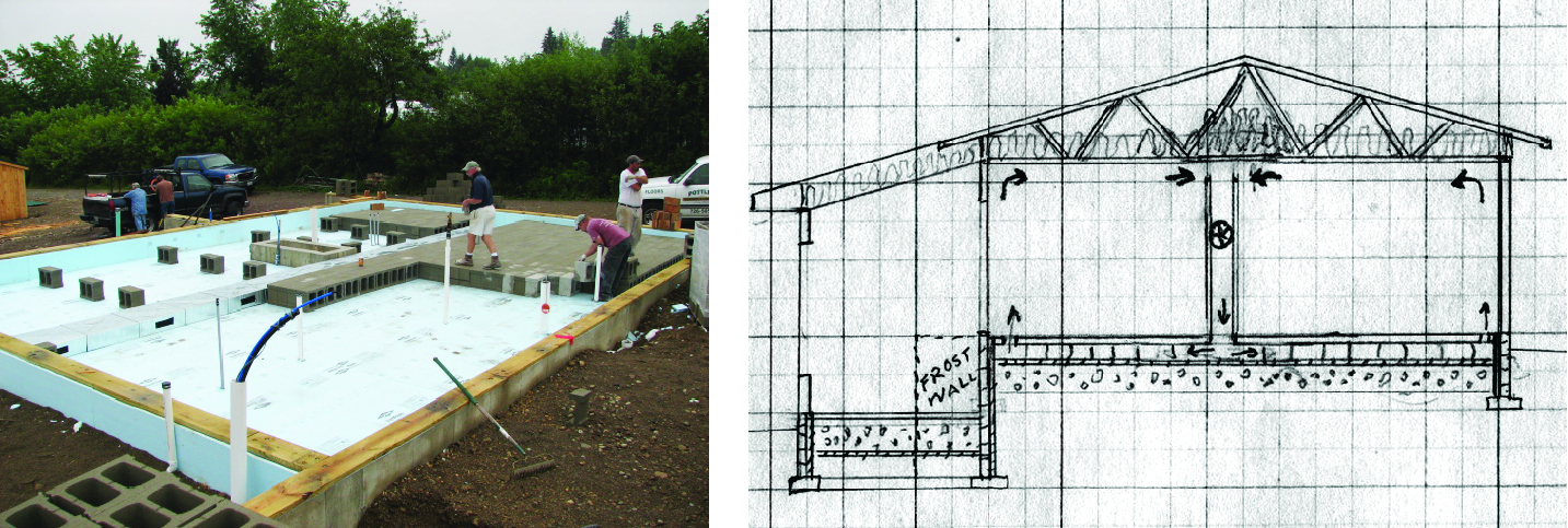
Figure 18. Thermal mass in the Maine house: laying the block (left), cross-sectional sketch (right)
The Kachadorian design calls for calculating the slab floor thickness so that the heat storage capacity of the floor and block mass matches the solar heat production capacity of the south window glass. The intent is to avoid excessive solar heating. This is an example of the calculation overkill that we think is common in the passive solar literature. We built almost the maximum glass area possible into the south wall and poured a standard four inch thick concrete floor. We see excess solar heat in the winter as a minor problem that can be solved by cracking open a window. In the summer, the roof overhangs and the movable insulation keep out direct sun. The night air flow from open windows cools the thermal mass, which holds down the temperature inside during the day.
Movable Insulation. Available capital and the predictable geometry of frame construction allowed us to use a combination of commercial and custom built solutions that insulated windows and doors to the high energy efficiency standard of the other passive solar elements in the design. Wherever there was sufficient wall space, the carpenters built hinged shutters that seal tightly when closed and open back against the wall. The wood frames and faces of the shutters enclose rigid foam insulation board an inch thick. On the larger windows on the south side there was no wall space for shutters, so we used commercially available movable insulation in the form of quilts that are stored on rollers above the windows and slide down on tracks that provide a tight closure.
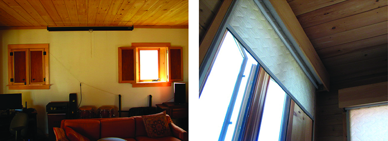
Figure 19. Movable insulation in the Maine house: shutters and quilts on rollers
Air Control. Because we were able to afford windows and doors that seal well, it was worth making the rest of the house airtight as well. In addition to the plastic sheeting on the inside surface of walls and ceiling that also served as the all-important vapor barrier, we caulked and taped liberally in critical places like joints between walls and ceiling and floor and around window and door frames. We used special electrical boxes made to be airtight and allow taping to seal them to the vapor barrier.
A house built this tightly often needs an air intake in the design. The wood fires that furnish supplemental heat and the breathing inhabitants both need fresh air. As in the New York house, outside air passes through an underground pipe that moderates its temperature and enters close to a centrally located chimney that serves a fireplace on one side and a wood-fired kitchen range on the other. This way the air that feeds the fires travels a short distance and creates little draft. The central chimney breaks the living space into two rooms while keeping the open plan that helps distribute heat around the house. This chimney location also adds to the thermal mass and keeps more of the heat from the chimney inside the house than a chimney on an outside wall. This chimney arrangement brings our cast iron, wood-fired kitchen range closer to the high energy efficiency of a masonry stove at a fraction of the price.
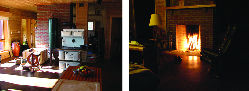
Figure 20. A central chimney partitions the open floor plan and services the kitchen range and fireplace, which provide all the wood heat in the Maine house
Overhangs. On the principle that overhanging roofs on all sides are good weather protection for the walls, windows, and doors of a house and sometimes for things stored outdoors, our policy has always been to design for them wherever possible. Because the raised truss in this house adds height to the roof at the eaves, we made the roof overhang nearly 3 feet in the attempt to shade the southern windows from the summer sun. The photo of the whole house that begins this section, taken in October, shows that despite the long overhang it permits the cold season sun to shine on the whole south window area. Some summer sun does penetrate the interior despite the overhang, but it can be stopped by lowering the insulated window covers.
Performance Comparisons
Hot water. The summer and winter hot water systems operate on the same principles as in the New York house, and the winter system uses the same stove and tank, brought from New York. Because we chose vertical glazing for the greenhouse (these are the windows on the left in the photo of the house in Figure 14), a solar collector for the summer system was placed outdoors where it can be angled properly. We located a standard insulated electric hot water tank (not electrified) inside the house, as close as possible to the solar collector to keep the convection loop short and maximize hot water accumulation. Because of the insulation and a larger tank, the Maine system stores more hot water longer than the bare tank in New York, enough for two days use after a half day of sunlight.
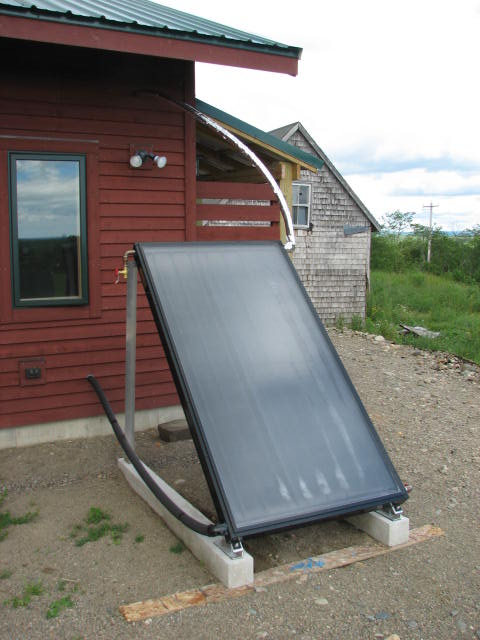
Figure 21. The flat plate collector for summer hot water at the Maine house is drained in winter
Attached greenhouse. We improved the solar functions of this greenhouse over the one in the New York house. We chose vertical glazing to permit the use of easily installed, commercially available movable insulation. Hence the large area of glass in this greenhouse can maximize the retention of the solar heat that it captures. Wide French doors between the greenhouse and the house living space allow us to better regulate airflow and create a temperature difference between them if so desired. The outside door that we put in this greenhouse greatly improves plant growing and summer ventilation. To provide easy external access, we put the greenhouse floor at ground level and also built the room partly into the hillside to preserve most of the earth-sheltered design of the greenhouse in New York, which has a sunken floor.

Figure 22. The Maine greenhouse in late fall
Critical components. Although the New York house has considerably more thermal mass and south glass, the Maine house outperforms it for several reasons. In a passive solar design, all the elements must work together; weak links in any system limit the performance of the whole. In the Maine house, all the elements are of sufficient quality to perform their functions equally well. It is better insulated and much more airtight. The thermal mass stores heat more effectively because the fan continually moves air through it. There is virtually no heat stratification: it is a one storey house, and stored heat radiates up from the floor while the fan moves rising warm air down from the ceiling through the thermal mass, which tends to equalize temperature everywhere. The movable insulation is designed to close more tightly as well. Finally, it has an improved attached greenhouse as described above. However, all these improvements are working against the colder winter (10 °F colder) and shorter winter days of the higher latitude in Maine (45° N).
| Heated floor area | 1250 ft2 |
| Wall insulation | R = 40 |
| Roof insulation | R = 60 |
| Foundation insulation | R = 20 |
| Thermal mass | 1300 12 inch concrete blocks under floor and 4 inch poured concrete floor |
| South-facing glass | 162 ft2 |
| Other glass | 78 ft2 |
Table 2. Specifics (Maine House)
| Extra Insulation and Wall Thickness | $10,000 |
| Window quality (thermopane and airtight) | $5,000 |
| Thermal Mass | $4,000 |
| Movable Insulation | $6,000 |
| Total | $25,000 |
| Percent of Total Construction Cost | 15% |
Table 3. Extra Construction Costs for Passive Solar (Maine House)
One test of a passive solar design is how well it holds heat overnight on cold winter nights without any supplemental heat (our practice in all the houses was to let the wood fires go out by 8 p.m.). By morning, the temperature in the NY house was dropping from 72 °F to as low as 55 °F as the winter wore on. By contrast, the Maine house stayed close to room temperature overnight until a December week of outside temperatures in the single digits. By the end of that week, the overnight drop was to 65 °F. As outside temperatures returned to normal in January, the overnight drop inside the house decreased, and the inside temperature on waking was around 69 °F.
How much more does passive solar design cost? That can vary with the way the design principles are applied and the materials a specific design requires. The extra costs in the Maine house reflect the expense of new materials and professional labor throughout the house, but the solar fraction of the total construction cost was still a low 15%.
Conclusion
The goal of this account was to demonstrate a number of ways that the same passive solar design principles can be applied to maximize residential energy savings with the least cost and technical difficulty. How will these ideas play in Tompkins County? Two Ithaca architects who reviewed my design for the Maine house said that apart from a small network of owner-builders that is applying a low-technology approach, there is not yet much passive solar construction or renovation in the county despite its overpopulation of intellectual heavyweights and its reputation for progressive politics. Current interest in “green design” tends to run to solar and wind electric technologies that replicate the push-button convenience that our society is used to but are very inefficient ways to heat a building. While this approach bestows a certain social status, it is so expensive that it is not a model likely to gain widespread adoption in an industrial economy now headed into long-term decline. Area developers sometimes promote “green materials” that may also confer status but rarely save as much of the planet as simple construction designs that dramatically reduce residential energy use.
Hence readers whom this saga encourages to “walk the talk” of sharply reduced residential energy use may be viewed as oddballs until resource depletion forces the rest of the community to see them more as heroic pioneers. Because their houses achieve so much with so little in the way of complicated equipment, a common reaction may be disbelief, and the community may not take seriously their overly “magical” accomplishment. Community interest in the houses described here, built over a forty-year period, has been low.
However, the tide may be turning. Our head carpenter on the Maine house monitored the condition of the unheated, unmanaged residence during the winter before we moved in. When he found that its temperature never dropped below 45 °F, he was so amazed that he reported his discovery widely. As the news percolates throughout this rural Maine community, habituated to burning through mountains of firewood or fossil fuel to get through New England winters, how will they see us, as tricksters or alchemists, or as models for the future? Meanwhile our carpenter, who knows, as builder of the house, that there is no magic involved, proudly announced that he has installed movable insulation on the windows of his own home.
Glossary
- Biomass burning
The most efficient use of biomass energy, as in heating directly by burning wood. Conversion of biomass to other forms like liquid fuels or electric or steam power involves a great waste of the energy in the biomass.
- Biomass energy
Energy from biological sources. Historically, wood has been the main source. This energy is renewable if harvested sustainably because it originates in the sun.
- Convection loop
The circuit that fluids like air or water make that transfers heat. When heated lower in the loop, the fluid becomes lighter and rises, moving the rest of the fluid around the loop. In the hot water systems described here, placement of a tank near the top of the loop allows continual accumulation of heated water in the tank by convection without an external source of energy to move the water.
- Earth-sheltered house, earth berm
An earth-sheltered house is a house partially surrounded by earth, either because it is built partly underground (e.g., into the side of a hill) or because one or more of its walls are backed by an earth berm, earth pushed up against a wall. In either case the earth adds insulation value, partly because the temperature underground is much higher than average winter air temperatures in the Northeast, typically 40-50 °F in a completely sunken basement
- Fossil fuels
Oil, gas, and coal, which are the fast-depleting nonrenewable energy sources on which industrial society is heavily dependent.
- Insulating glass, thermopane
Glazing with two or more layers of glass sealed together so that air or other gas held between the layers acts as insulation.
- Masonry heaters
The most efficient woodstoves because they allow hot, efficient burns and they retain most of the heat in the masonry, heat that is lost up the chimney in other woodstoves.
- Movable insulation
Designed to easily cover windows on the south side to prevent heat from escaping when the sun is not shining in, insulating covers also function to block excess sun in summer and to insulate windows on other sides of the house when daylight is not needed. Inside and outside cover designs are both used, but mine have all been inside. Unlike curtains, these essential components of passive solar design must seal to the window frame on all sides when closed to function properly as insulation.
- Passive solar
Building design that uses the sun to provide space and water heating with little or no external energy inputs or technologically expensive materials. For example, electrical components like converters, batteries, pumps, and fans are mostly unnecessary.
- Solar greenhouse
A greenhouse that incorporates as many of the elements of passive solar design as possible.
- Rumford fireplace
An energy-efficient design used in colonial times for cooking and heating.
- R values (e.g., R=28)
A universal measurement of insulation value of materials. For example, rigid urethane has a relatively high R value of R=8 per inch of thickness. I insulated the New York house entirely with rigid urethane, most of it discarded by a company that cuts up large buns of the stuff to order for clients. I got the discards for free.
- Thermal mass
A heat storage material that is an essential component of passive solar design. Water and metal store a lot of heat but stone, brick, or other masonry are the most common because they can function as structural elements of buildings and still store more heat than most building materials.
Notes
[1] Following the historical pattern of human exploitation of all finite resources, fossil energy extraction started with the sources easiest to tap and has progressed toward sources that are the most expensive, because they are lowest in quality and hardest to extract from the earth. Hydraulic fracturing is an example of an expensive extraction methodology that guarantees a higher cost of production over the long run. This increasing cost will make fossil fuel prohibitively expensive for more and more uses, eventually including residential heating.
[2] Kachadorian, James. The Passive Solar House: Using Solar Design to Heat and Cool Your Home. Chelsea Green, 1997.